If you are a game developer, you are aware of the usefulness of a blur effect in highlighting important elements on the screen or creating a sense of depth in the UI. This tutorial will guide you through the process of creating a UI blur in Unity using Shader Graph, a node-based shader creation tool. You will find it easy to follow, and the end result can significantly enhance the professional look of your game. So, let’s dive in and create an amazing UI blur! Enjoy the tutorial!
Project Structure
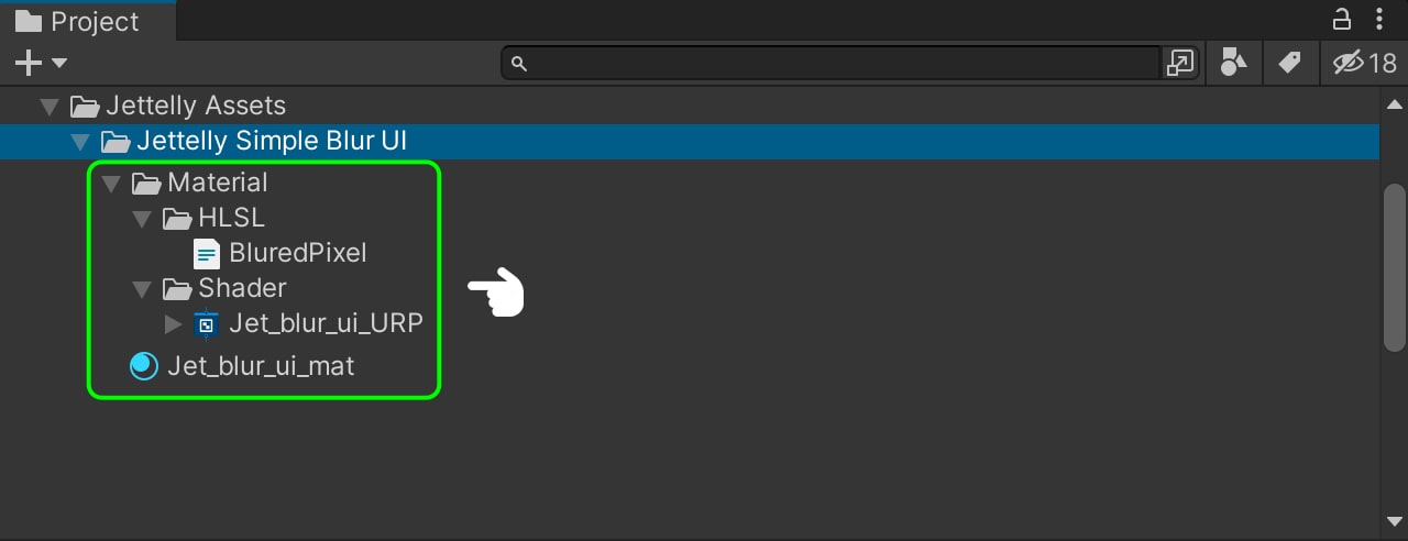
To organize our project, we are going to create a main folder called ‘Jettelly Simple Blur UI.’ Inside this folder, you can see all the subfolders used in the project (see image). The structure of the subfolders can be organized according to your preferences, but it is important to maintain order in any project.
Shader & Material setting
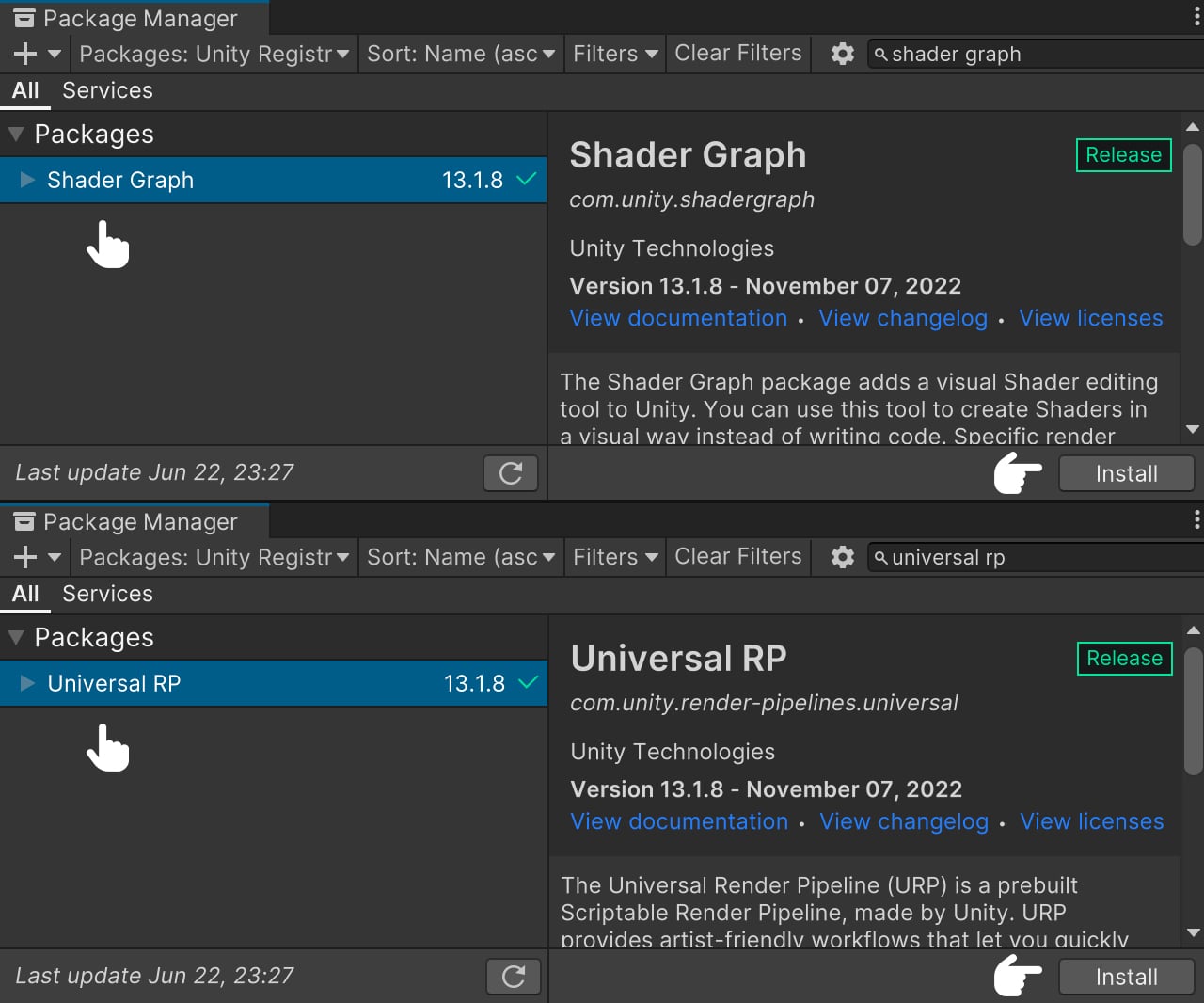
Before we get started, it is essential to install the necessary dependencies to ensure our shader functions properly: Shader Graph and Universal RP. Shader Graph enables us to program our shader using nodes, while Universal RP guarantees accurate display within our game. To install these dependencies, follow these steps: Go to Windows > Package Manager. In the opened window, search for both dependencies and proceed to install them.
To start, we need to search for Shader Graph and select the latest available version. After selecting the version, we can proceed with the installation. Next, we search for Universal RP and select the most recent version before proceeding with the installation as well. Once both installations are complete, we can safely close the window.
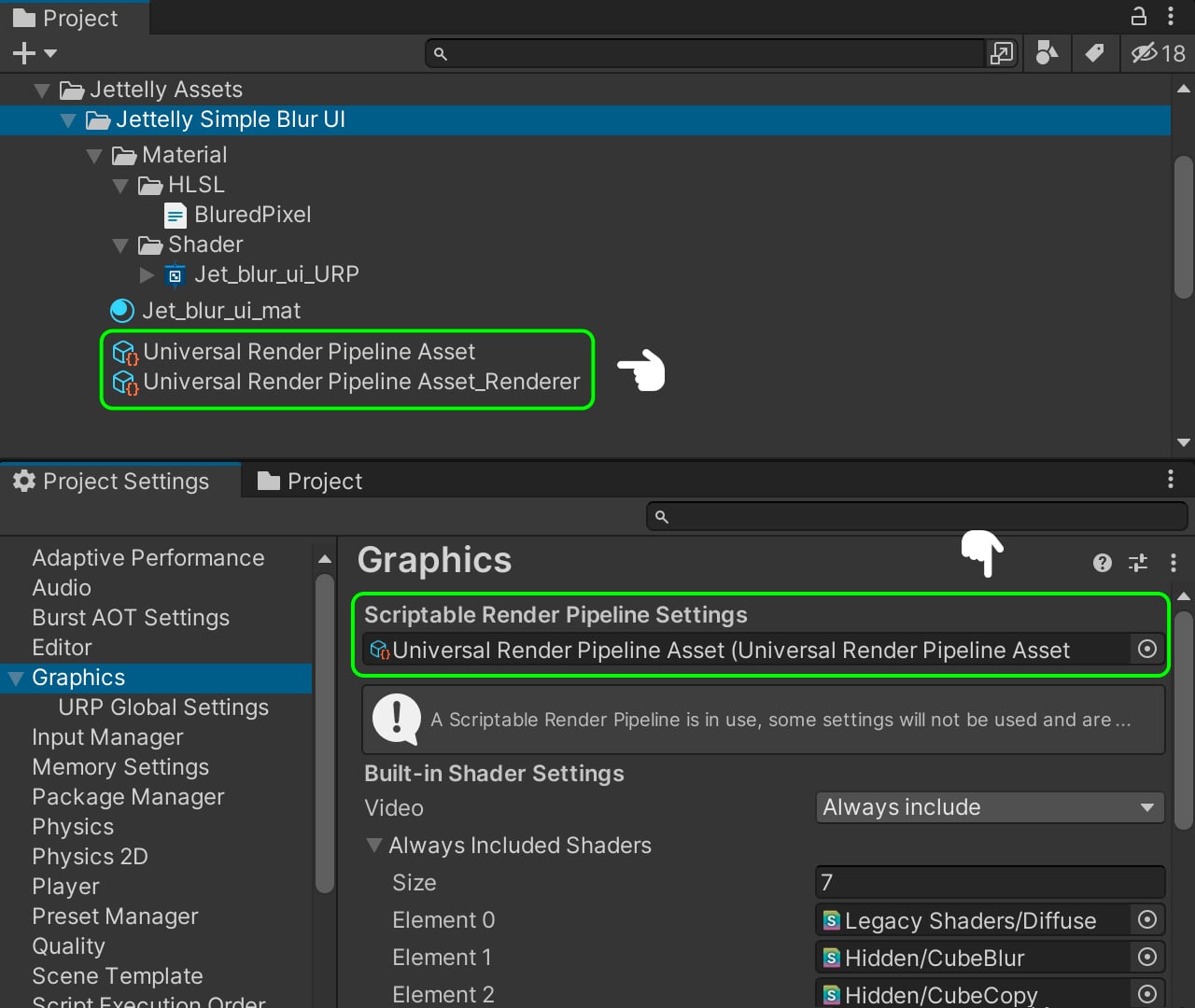
After successfully installing the required dependencies, we can proceed to create a new Render Pipeline for our project. To do this, follow these steps: Navigate to Create > Rendering > Universal Render Pipeline > Pipeline Asset (Forward Rendering). Afterward, go to Edit > Project Settings > Graphics and select the Scriptable Render Pipeline Setting. From there, we can choose the previously created Render Pipeline.
Next, within our UniversalRenderPipelineAsset, we need to enable the following properties: Opaque Texture and Opaque Downsampling.
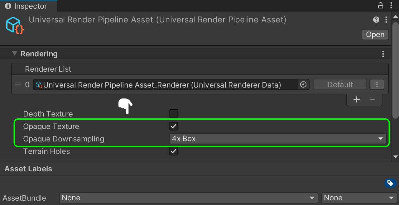
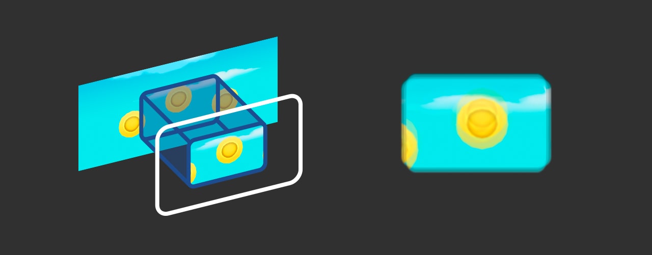
The Opaque Texture feature enables us to generate a _CameraOpaqueTexture. This means that our camera will capture a screenshot, and subsequently, we can utilize the shader to project it onto our UI image.
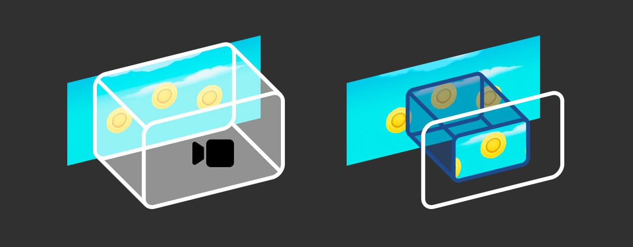
The Opaque Downsampling feature enables us to reduce the resolution of this texture without significantly impacting the GPU performance. Using a downsampling factor of 4X means that the texture will have a quarter of its original resolution on the GPU, resulting in faster and lighter processing. This feature is especially beneficial for mobile devices.

Next, we need to create our Shader and Material. To do this, we create an Unlit Graph shader by navigating to Create > Shader > Unlit Shader and naming it ‘Jet_blur_ui_URP.’ Following that, we proceed to create a material by selecting Create > Material naming it ‘Jet_blur_ui_mat’.
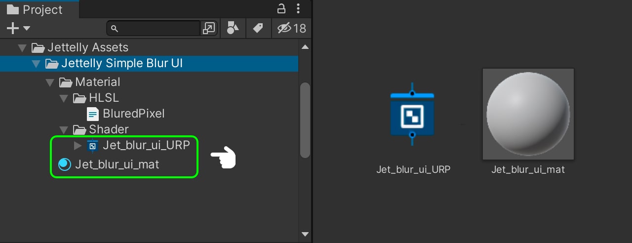
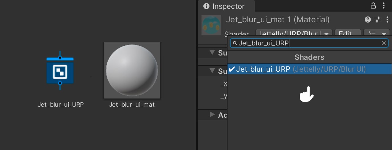
We assign the shader to the material from the Material Inspector.
Creating the scene
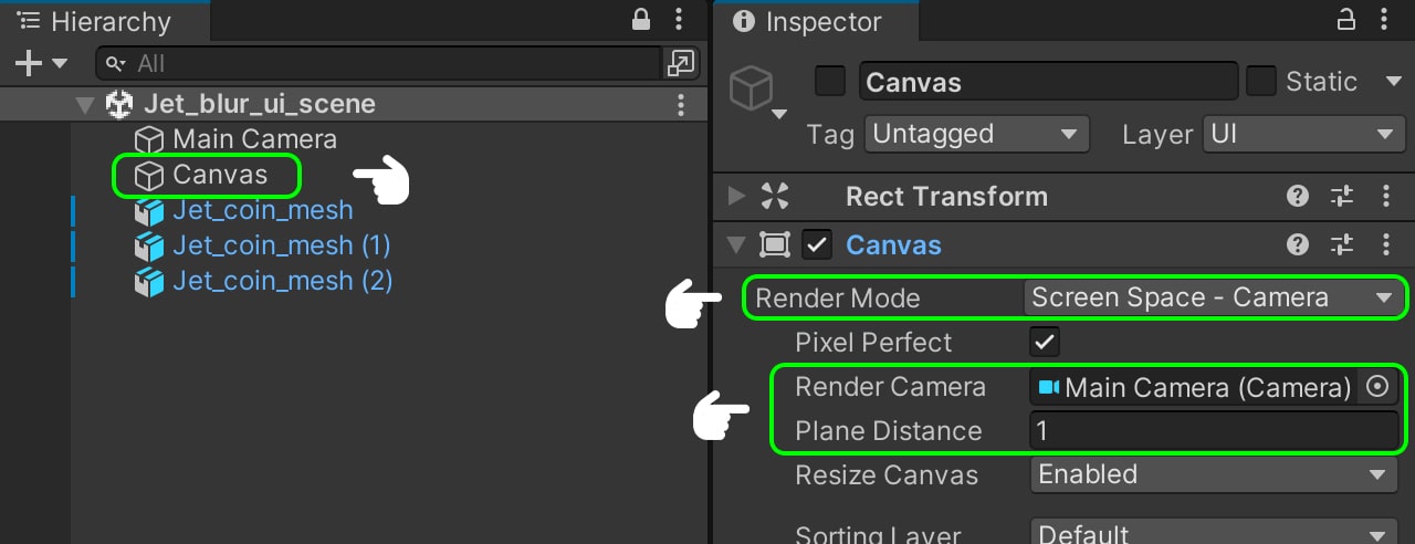
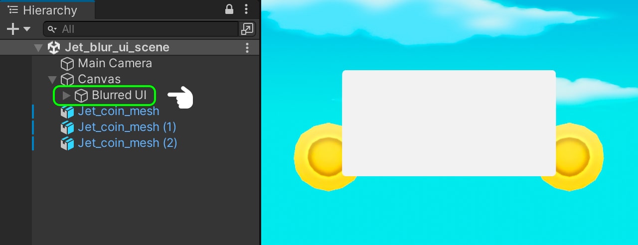
In our scene, we previously created a 3D composition and added a Canvas (GameObject > UI > Canvas) to house our UI elements. We configure the Canvas as Screen Space-Camera and set our Main Camera as the Render Camera. Additionally, we adjust the Plane Distance to 1 meter, ensuring that the canvas remains positioned at a one-meter distance from the camera.
Within the Canvas, we create an Image (GameObject > UI > Image) named ‘Blurred UI.’ To better visualize the results, we increase its size accordingly. This panel is the target for our blur effect, which is why we assign the ‘Jet_blur_ui_mat’ material to it.
Creating the blur effect
We open our ‘Jet_blur_ui_URP’ shader and proceed to create our Samples. To achieve this, we utilize the Scene Color node. This node grants us access to the camera’s color buffer, allowing us to store the colors currently visible to the camera. In essence, this node functions similarly to taking a screenshot. However, in order to apply this captured image onto a mesh, we require the mesh’s UV coordinates. To obtain these coordinates, we introduce the Screen Position node, which provides the position of the mesh vertices in screen coordinates. By connecting the Screen Position node with the Scene Color node’s UVs, we obtain the camera’s projection on the texture where we are applying the shader.
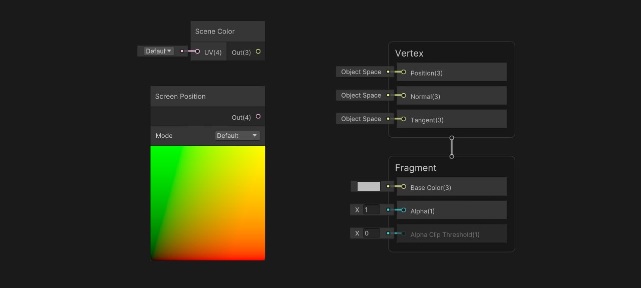
Before connecting the Screen Position node, we need to add Samples and several functions to generate UV offsets for achieving the blur effect. Each Sample represents a duplicate of the color buffer, meaning that using 8 samples will involve passing 8 copies of the color buffer. However, this process can be computationally expensive for the GPU, as it is equivalent to passing 8 textures for a single image. To mitigate this, we configure the Downsampling to 4X Box in the UniversalRenderPipelineAsset settings. The 4X Box downsampling allows us to pass only 1/4th of the resolution for each sample used, reducing the computational load while maintaining quality.
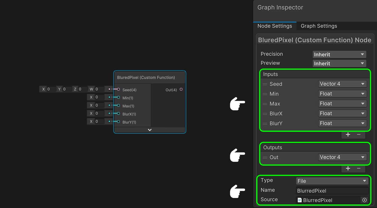
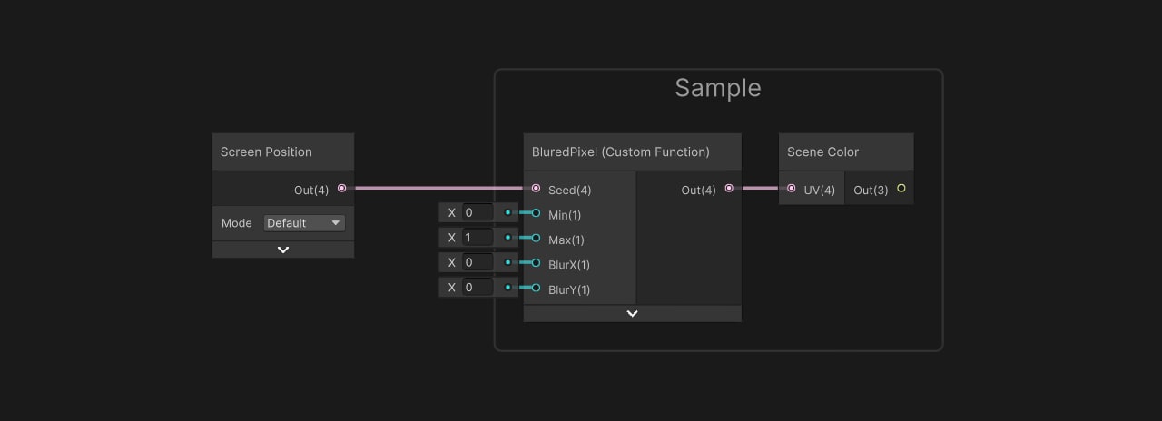
To generate the offset between the samples, we need to create an HLSL function and pass it to a Custom Function node. To create the HLSL file, open Visual Studio and navigate to the Jettelly Simple Blur UI folder. Right-click and select ‘New File’ to create a new file. Name the file ‘BlurredPixel’ and ensure that its extension is ‘.hlsl.‘ The BlurredPixel function has multiple inputs: ‘Seed’ receives the Screen Position node, ‘Min’ and ‘Max’ serve as noise interpolators, ‘BlurX’ and ‘BlurY’ allow us to adjust the amount of blur in the UV coordinates, and ‘Out’ represents the output of the operation. Save the file and return to Unity.
void BluredPixel_float(float4 Seed, float Min, float Max, float BlurX, float BlurY, out float4 Out)
{
    float randomno =  frac(sin(dot(Seed.xy, float2(12.9898, 78.233))) * 43758.5453);
    float noise = lerp(Min, Max, randomno);
    float x = float(sin(noise)) * BlurX;
    float y = float(cos(noise)) * BlurY;
    float4 uvpos = float4(Seed.x + x, Seed.y + y, Seed.zw);

    Out = uvpos;
}
In the ‘randomno’ variable, we store a randomly generated value. Next, in the ‘noise’ variable, we create noise by interpolating between the minimum and maximum values of the random value. We then proceed to create ‘uvx’ and ‘uvy’ variables, where we multiply the sine and cosine of the noise by the blur amount in their respective coordinates. This step allows us to increase or decrease the blur intensity. Finally, ‘uvpos’ generates an offset for both the U and V coordinates of the UV. We can now return to our shader.
In the Custom Function configuration, we pass our BlurredPixel file as the Source and use the name ‘BlurredPixel’ for it. However, errors have occurred in our node due to the absence of input and output configurations. To resolve this, we proceed to add the necessary inputs. First, we add a Vector 4 input named ‘Seed,’ followed by a Float input named ‘Min.’ Additionally, we include a Float input labeled ‘Max.’ We also create two Float inputs named ‘BlurX’ and ‘BlurY.’ Finally, for the output, we add a Vector 4 named ‘Out.’ With these configurations in place, our node now compiles without errors.
We connect the output of the Custom Function to the UV input of the Scene Color node. These two nodes combined represent 1 sample. To group them together, we select both nodes and right-click to access the context menu, then choose ‘Group Selection.’ For the Seed input, we pass the Screen Position node, and we set Min to 0 and Max to 1.
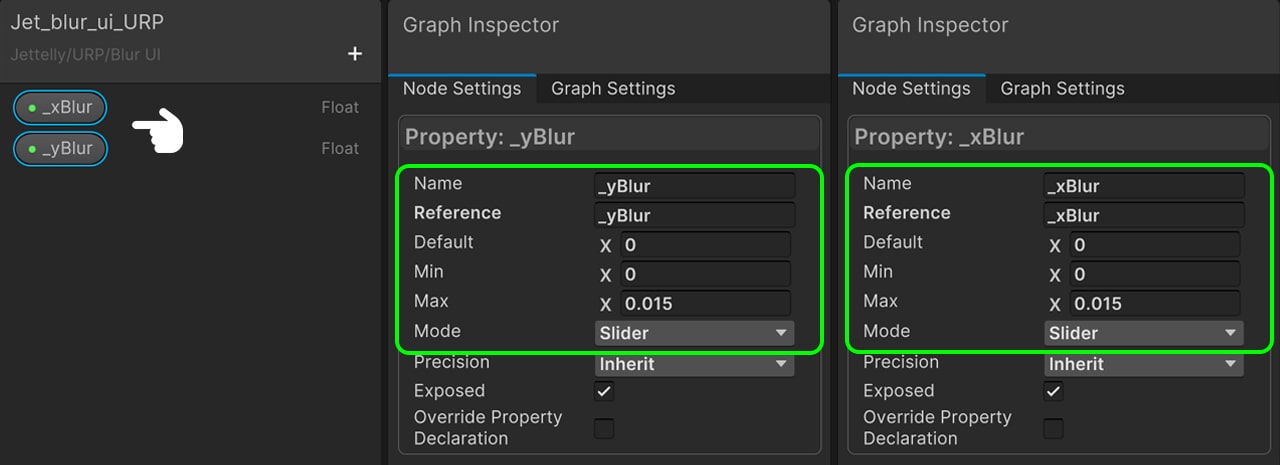
To enable the Blur effect, we need to create two new properties. To do this, we navigate to the Blackboard and create a Float input named ‘_BlurX.’ This property should be set as a Slider with a range between 0 and 0.015. Next, we create another Float input named ‘_BlurY,’ which should also be a Slider with a range between 0 and 0.015.
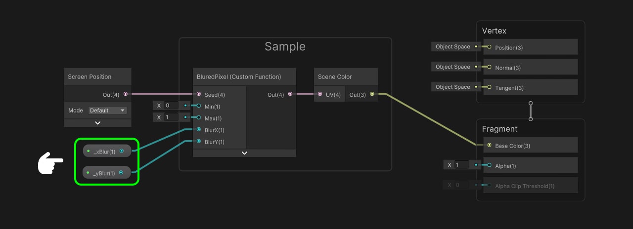
We proceed to drag both properties into the node area. We connect ‘_BlurX’ to ‘BlurX’ and ‘_BlurY’ to ‘BlurY.’ Then, we connect the output of the Scene Color node to the color input of the Fragment Shader.
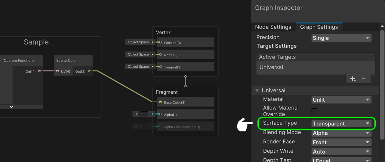
Set the Surface Type to ‘Transparent.’ Finally, we save the changes and move to our material.
When we modify the values of these properties, we will observe that an offset with noise is generated in the image. This noise contributes to enhancing the aesthetic quality of the blur effect. The only remaining task is to add more samples.

Returning to our shader, we duplicate the Sample node 6 times. For each Seed in the individual Samples, we pass the Screen Position node. Similarly, we repeat this process for the Blur properties, connecting ‘_BlurX’ to ‘BlurX’ and ‘_BlurY’ to ‘BlurY’ in each Sample node.
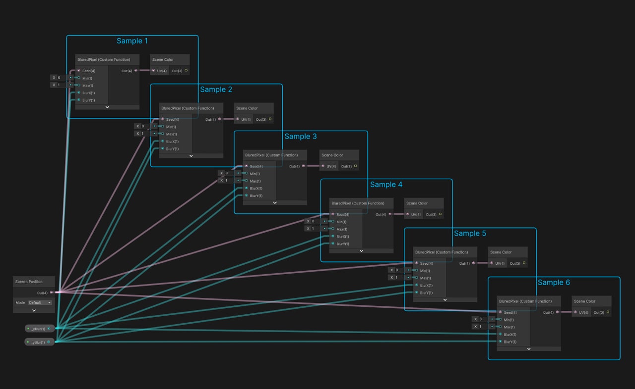
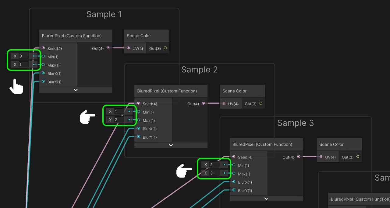
Now we’re going to generate a small variation in the noise in each sample, for this, we make the minimum and maximum of the second sample equal to 1 and 2, then 2 and 3, then 3 and 4 and so on.
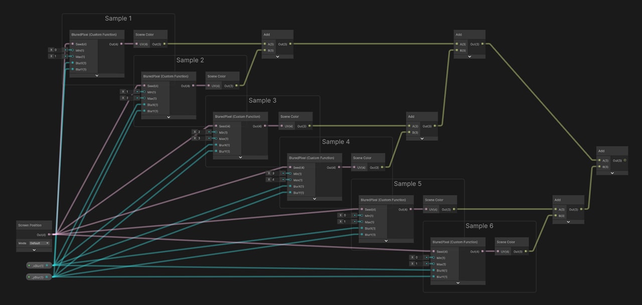
We have successfully implemented the blur effect, and now we need to connect it. This process is straightforward: We add all the Samples by using multiple Add nodes until they are all connected.
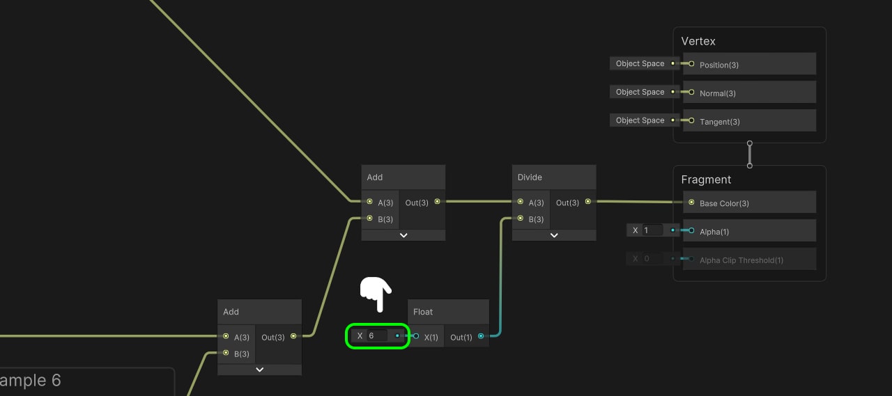
Prior to connecting the shader with our Fragment, it is necessary to divide the previous operation to prevent output saturation. For this purpose, we introduce a Divide node and a Float value. We connect the sum of the Samples as the first input and the vector as the second input. The value of the vector corresponds to the number of samples we previously created, which in this case is 6. We then connect the resulting value to the color input of the Fragment Shader, and save the changes.
As we can see now, our image is perfectly blurred. However, if we modify the color it does not work. We return to our shader.
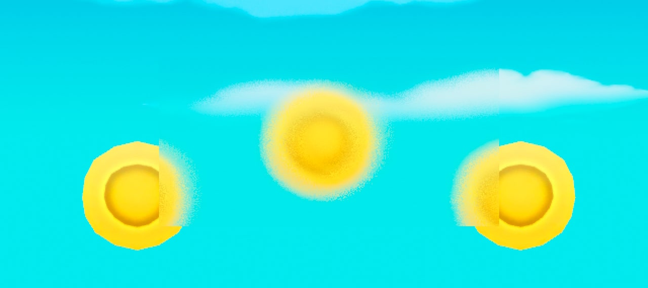
Adding Color
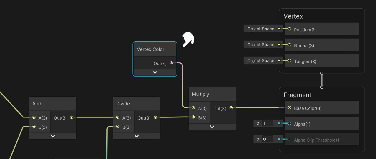
To modify the color we add a Vertex Color node and multiply it with the output of the division. We connect the result to the color input of the Fragment Shader and save.
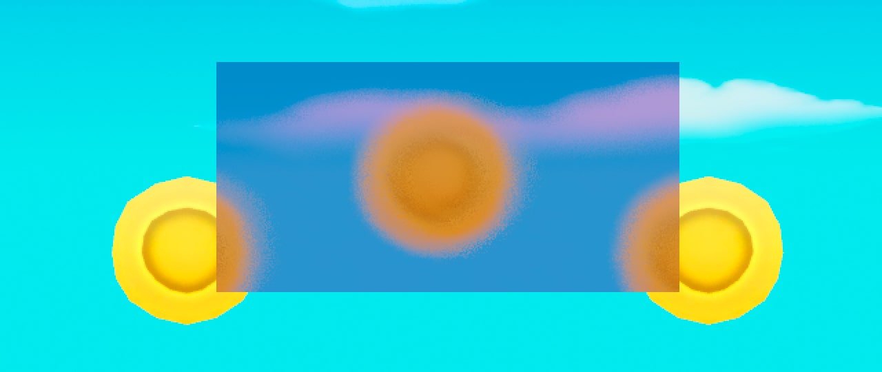
Final effect
Now we can modify the color of the image. Our shader is ready.
In conclusion, throughout this tutorial, we have learned how to implement a blur shader for our UI using Shader Graph in Unity.

