Welcome, racers! In the thrilling world of Mario Kart, Item Boxes are essential elements that add excitement and strategy to races. If you’ve ever wondered how to recreate the iconic Item Box in your own racing game in Unity, you’ve come to the right place. In this article, we’ll dive into the fascinating realm of Shader Graph and discover how to create an impressive visual effect for the Item Box, giving it that authentic Mario Kart touch. Join me as I guide you through the step-by-step process, so you can incorporate this element into your game and take the players’ experience to the next level. Get ready to accelerate in style!
Project Structure
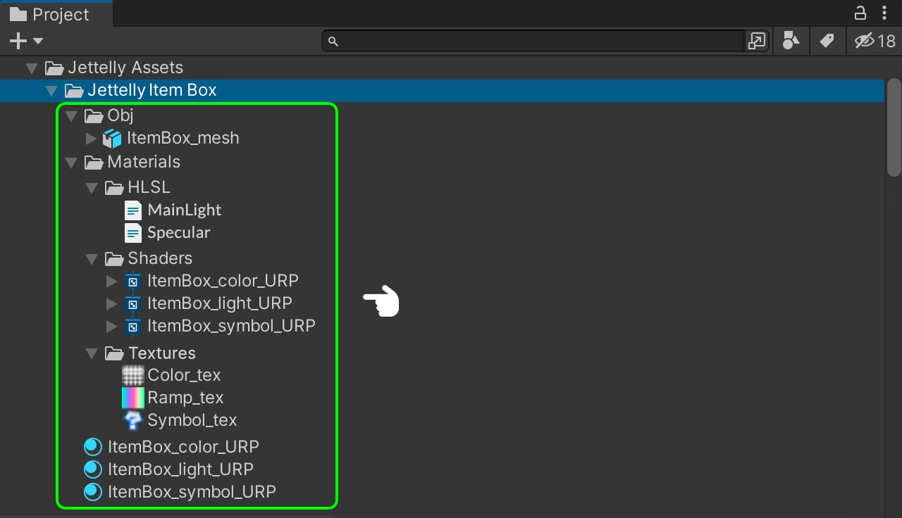
To organize our project, we are going to create a main folder called ‘Jettelly Item Box.’ Inside this folder, you can see all the subfolders used in the project (see image). The structure of the subfolders can be organized according to your preferences, but it is important to maintain order in any project.
3D Mesh & Textures
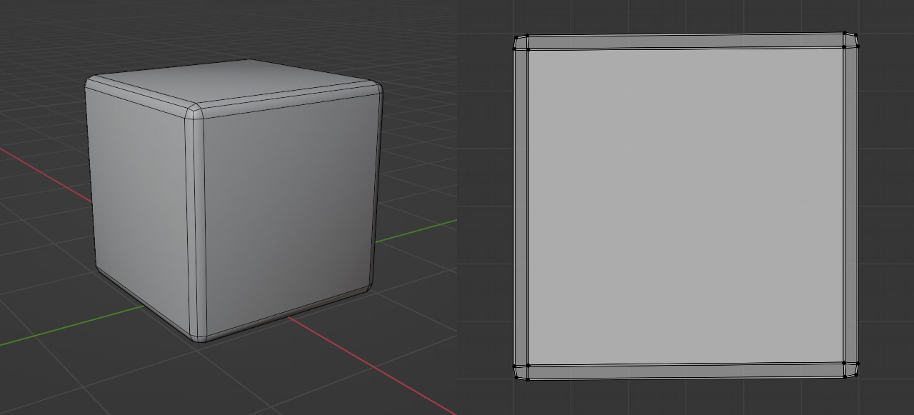
Mesh configuration in our 3D software (3DMax, Maya, Blender, other). In the case of UVs, the 6 faces of the cube are overlapping on each other. (Overlapping).
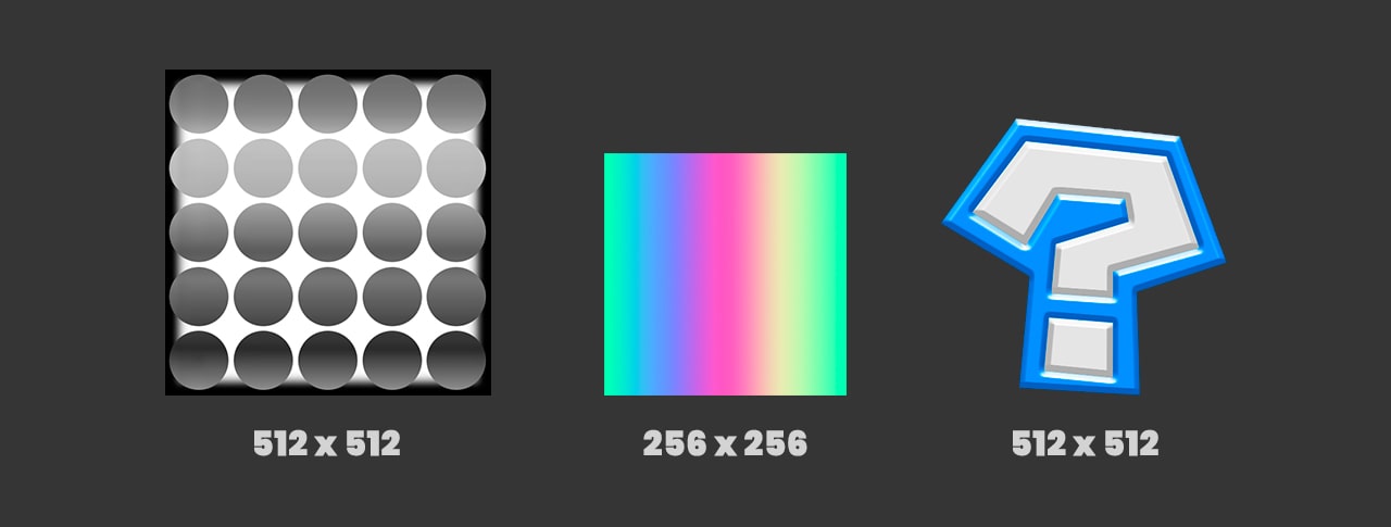
Sizes of the textures of our shader.
Shader & Material setting
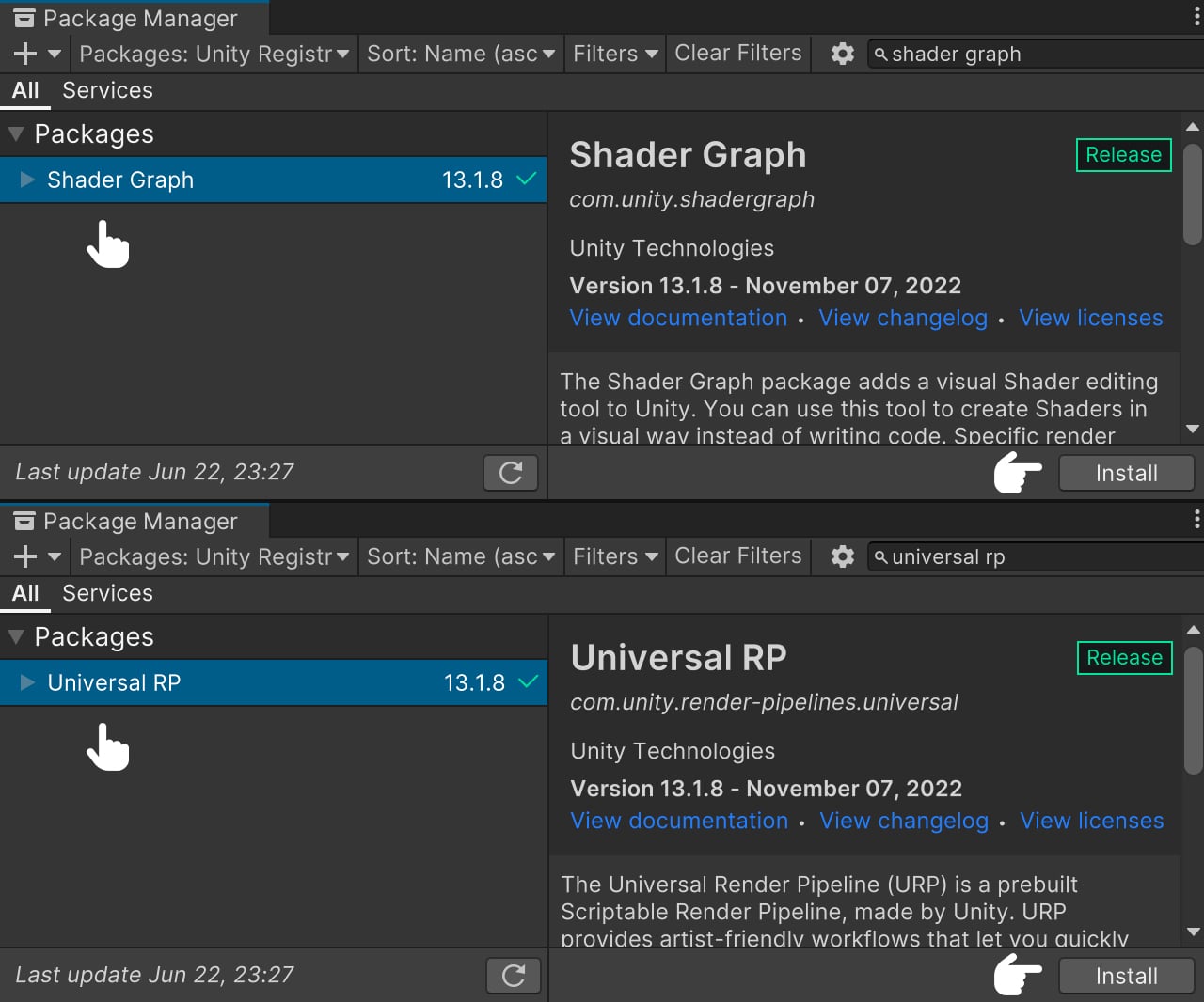
Before we get started, it is essential to install the necessary dependencies to ensure our shader functions properly: Shader Graph and Universal RP. Shader Graph enables us to program our shader using nodes, while Universal RP guarantees accurate display within our game. To install these dependencies, follow these steps: Go to Windows > Package Manager. In the opened window, search for both dependencies and proceed to install them.
To start, we need to search for Shader Graph and select the latest available version. After selecting the version, we can proceed with the installation. Next, we search for Universal RP and select the most recent version before proceeding with the installation as well. Once both installations are complete, we can safely close the window.
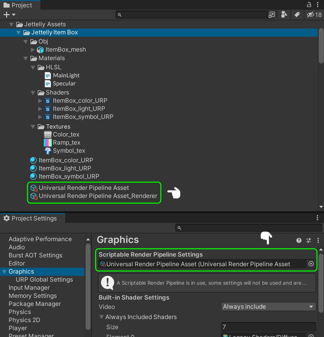
After successfully installing the required dependencies, we can proceed to create a new Render Pipeline for our project. To do this, follow these steps: Navigate to Create > Rendering > Universal Render Pipeline > Pipeline Asset (Forward Rendering). Afterward, go to Edit > Project Settings > Graphics and select the Scriptable Render Pipeline Setting. From there, we can choose the previously created Render Pipeline.
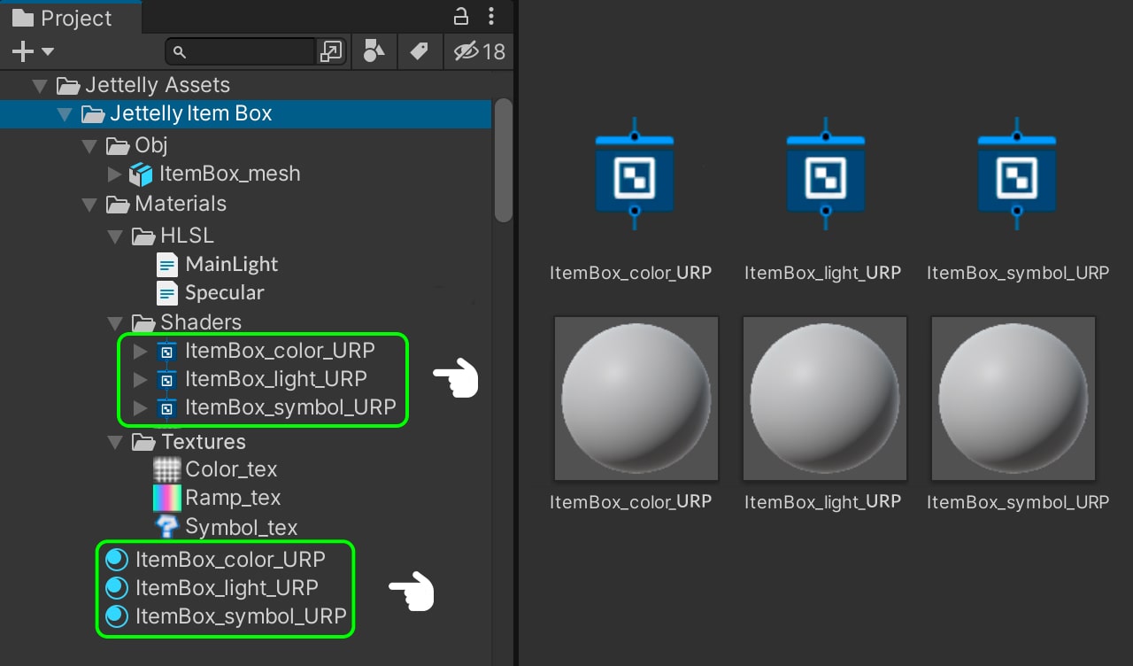
For this tutorial we are going to need 3 shaders and 3 materials: one for the color effect, another one for the lighting and finally one more for the symbol inside. For that reason we have to go to Create > Shader > Unlit Shader and naming it ‘ItemBox_color_URP.’ We repeat the process and create a new shader and naming it ‘ItemBox_light_URP.’ We repeat the process one more time and naming it ‘ItemBox_symbol_URP.’ Now we have to create 3 materials by selecting Create > Material and name them the same as our shaders.
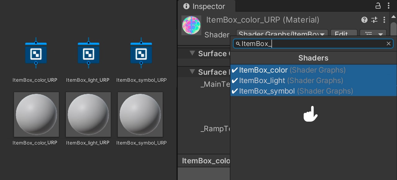
We select the materials, and in the Material Inspector, we assign the respective shaders.
Creating the scene
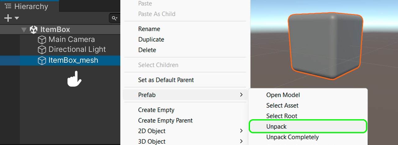
We start working with the color effect, to do this, we drag our ‘ItemBox_mesh’ to the scene, make Unpack Prefab, and then we assing the ‘ItemBox_color_URP’ material to it. We open our shader to configure the color effect in it.
Creating the color effect
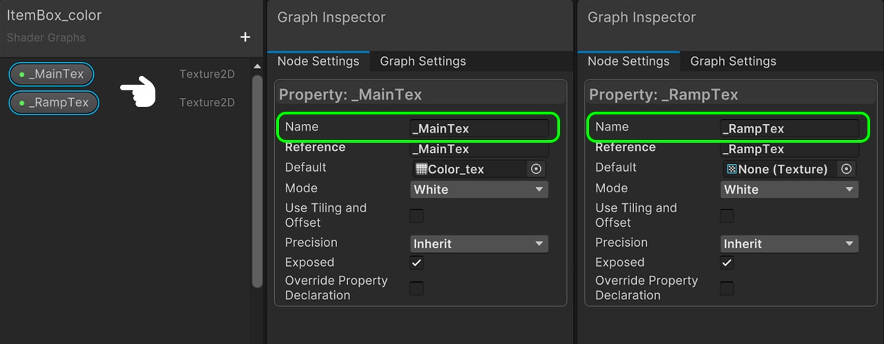
To create this effect we need 2 textures: One in grayscale and a ramp to position the colors in relation to the grays of the first texture. We go to the Blackboard and create a 2D texture. We call it ‘_MainTex,’ by default we put ‘Color_tex.’ Then we create a new 2D texture and we call it ‘_RampTex,’ by default we put ‘Ramp_tex.’ ‘_MainTex’ corresponds to the gray scale that we will use to distort the U coordinate of the UVs in the ‘_RampTex,’ in this way, we will achieve a colorful effect on it.
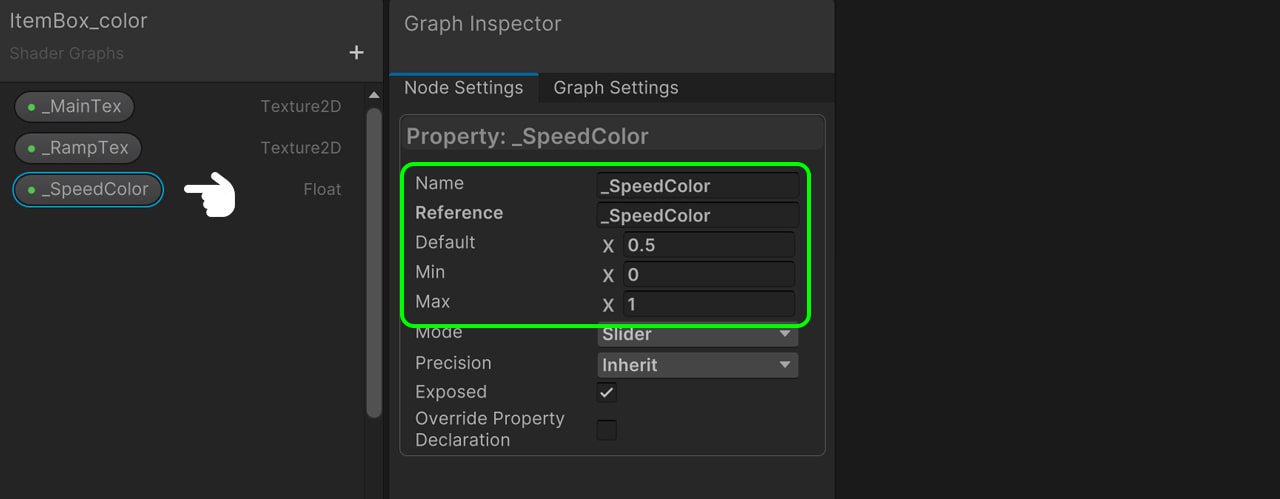
We will also add time. We create a Float to modify the speed of color movement. We will call it ‘_SpeedColor’ and it has to have a range between 0 and 1 with 0.5 by default.
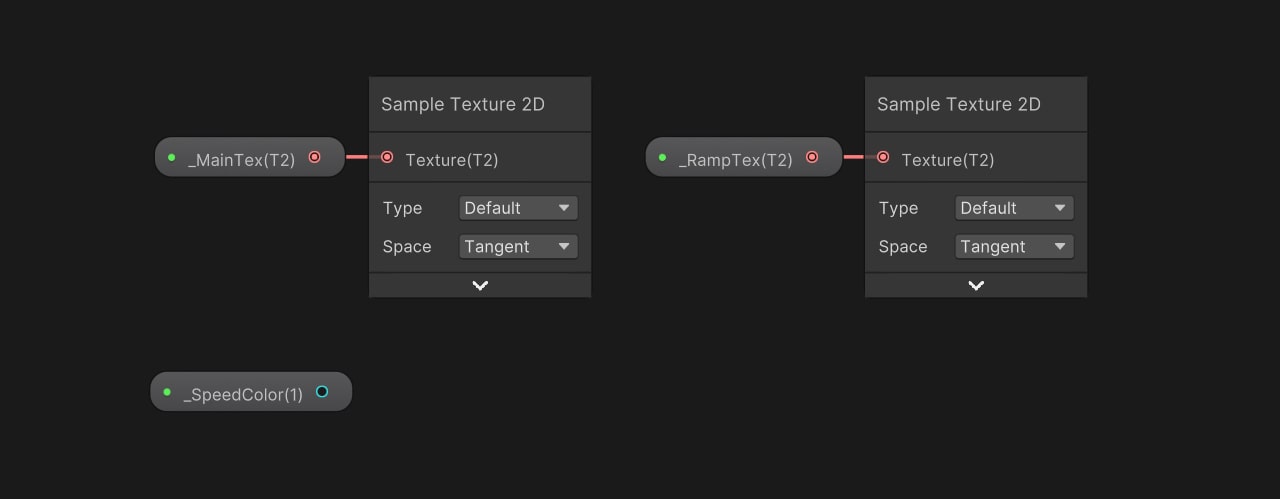
We drag our 3 properties to the node area. The first thing we do is to assign a Sample Texture 2D node for both the ‘_MainTex’ and the ‘_RampTex.’
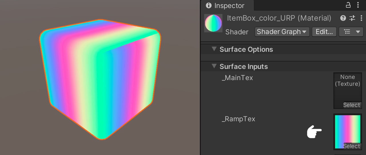
Select the material ‘ItemBox_color_URP’ and set the texture ‘Ramp_tex.’ Currently our mesh shows the faces on the outside. What we will do next is to render only the faces inside the cube. To do this, we will generate our Cull Front.
We add the Branch node, which returns true or false based on the predicate input. As the input, we pass the In Front Face node, which determines true or false depending on the face being rendered. We connect Is Front Face to the Predicate input and invert the values, mapping 0 to True and 1 to False. This effectively flips the Cull in the rendering. Next, we multiply this operation by the color output of the texture and connect the result to the color input of the Fragment Shader. Additionally, we introduce a Divide node and connect its input to the previous multiplication. The output alpha is connected to the alpha input of the Fragment Shader.
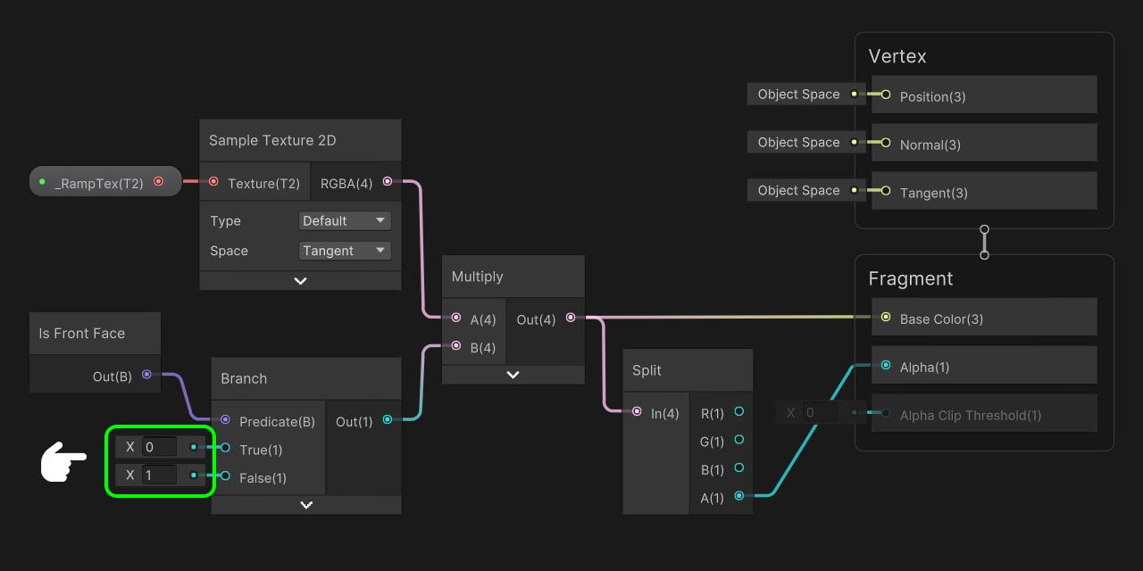
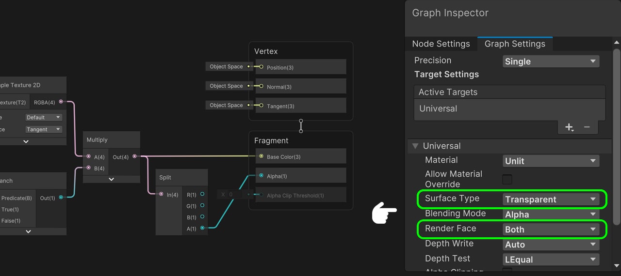
Then the Surface Type is set to ‘Transparent’ and Render Face as ‘Both’ and save.
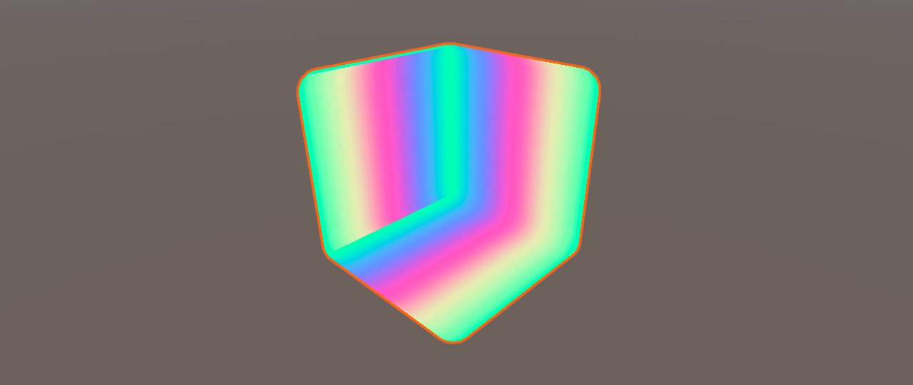
As we can see, now only the interior of our mesh is being rendered.
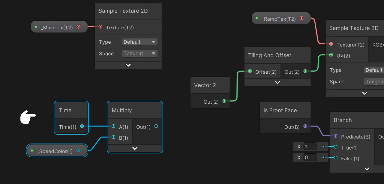
To configure the color effect, we need to deform the UVs of our ‘_RampTex’ by adding the grayscale texture and time. Use the Tiling and Offset node to achieve this, connecting it to the UVs of the ‘_RampTex’ texture. Bring a Vector 2 and connect it to the offset of the Tiling and Offset node, affecting only the U coordinate of the UVs.
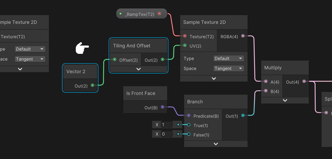
Now we have separated the coordinates. X is equal to U and Y is equal to V. What we do next is add the time, for that reason we bring the Time node. We multiply Time by ‘_SpeedColor’ to modify the offseting speed dynamically.
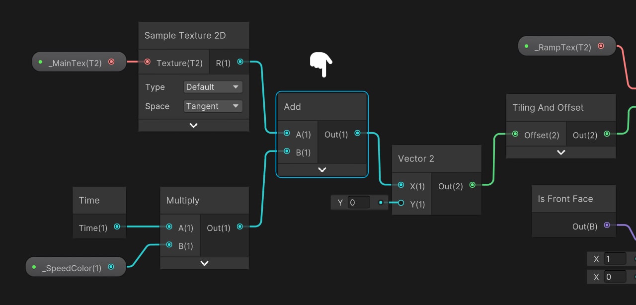
We add the red channel of the texture with the operation resulting from the multiplication of time by ‘_SpeedColor’ and connect it to the U coordinate of the ‘_RampTex’ and then save.
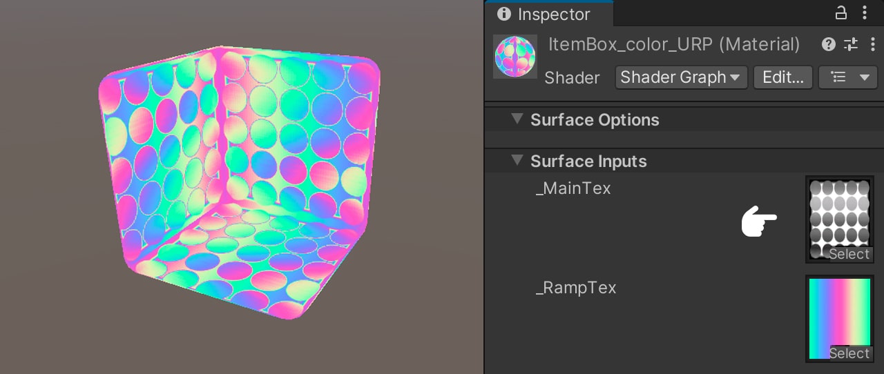
Select the material ‘ItemBox_color_URP’ and set the texture ‘Color_tex.’ Now we can see that the colors follow the pattern of this because now the UVs of the ‘_RampTex’ are being distorted.
Adding Fresnel and Specular
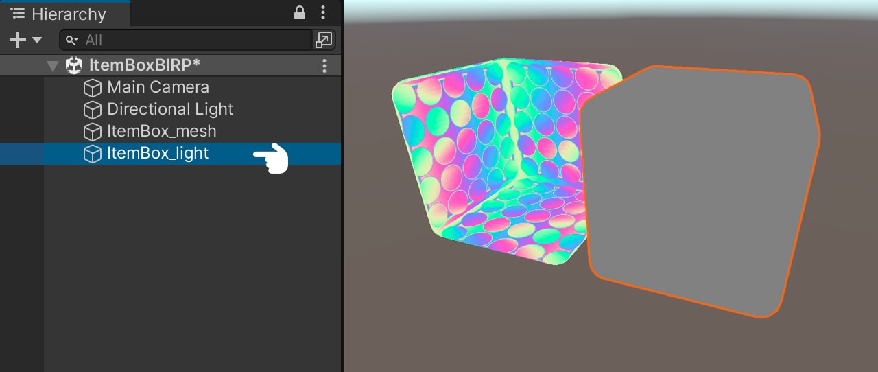
Now we will add the lighting, for this we duplicate the ‘ItemBox_color’ in our hierarchy, then we assign it the ‘ItemBox_light_URP’ material and rename it as ‘ItemBox_light.’ We open the shader.
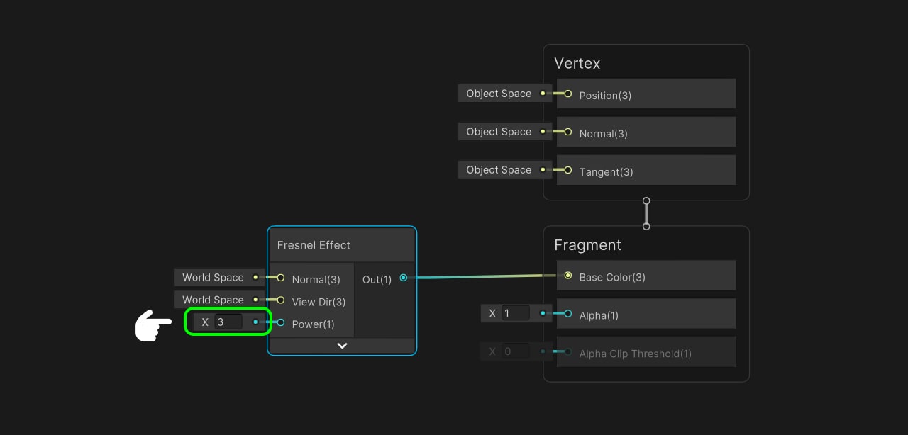
The only thing we will do for this shader is to add Fresnel and Custom Specular. We start by bringing the Fresnel node, then we set its power to 3 to be subtle, we connect the output with the color of the Fragment Shader.
We configure our Surface Type as ‘Transparent’ and Blending Mode to ‘Additive.’ We save.
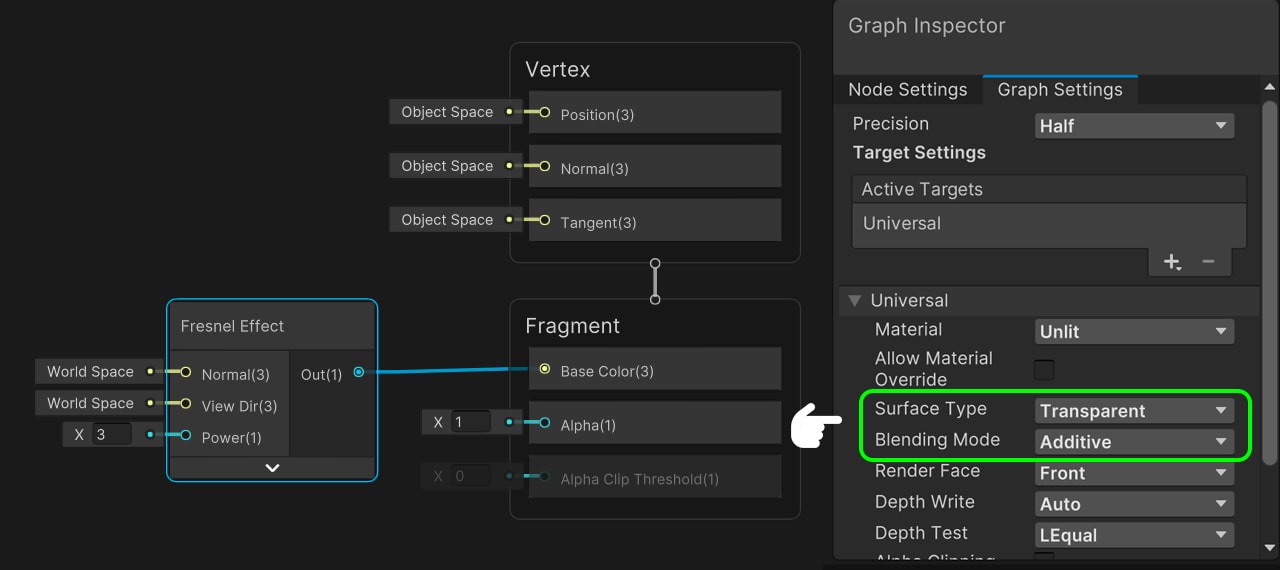
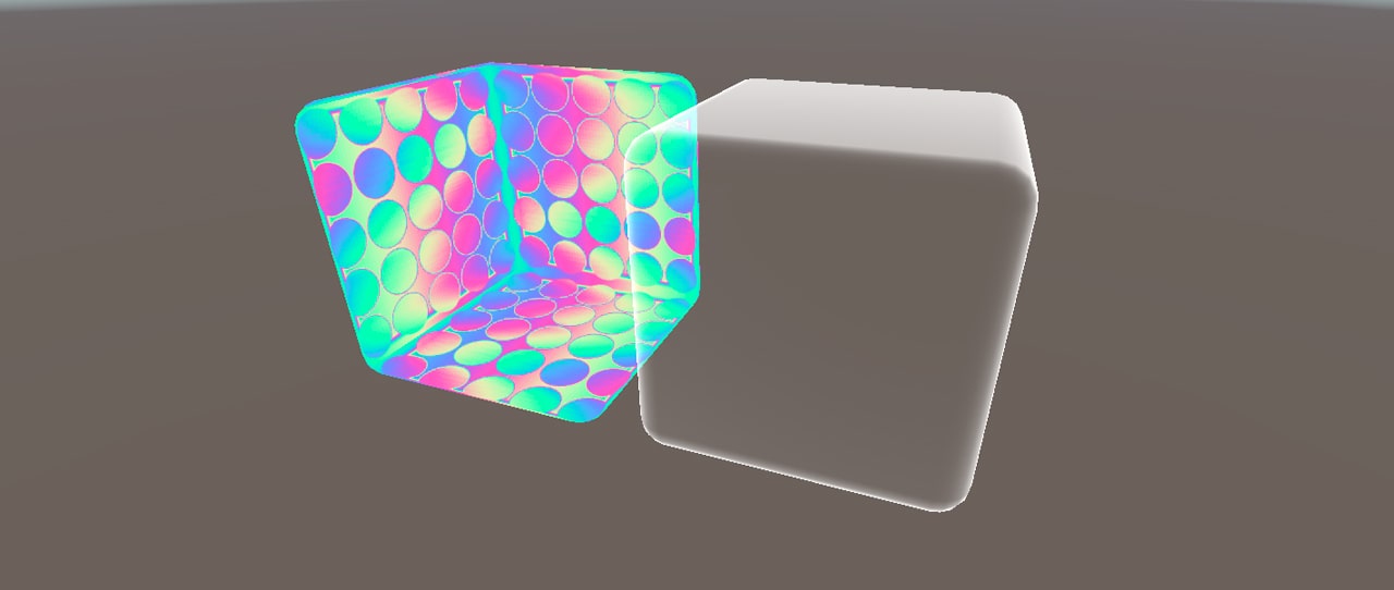
Up to this point we already have the color and the Fresnel effect done.
Now we are going to create the Custom Specular. For this we will use the hlsl ‘MainLight’ and ‘Specular’ files. To create the HLSL file, open Visual Studio and navigate to the Jettelly Item Box folder. Right-click and select ‘New File’ to create a new file. Name the file ‘MainLight’ and ensure that its extension is ‘.hlsl.‘ Do the same for the file ‘Specular.’
#ifndef MAINLIGHT_INCLUDED
#define MAINLIGHT_INCLUDED

void MainLight_half(out half3 Direction)
{
#ifdef SHADERGRAPH_PREVIEW
    Direction = half3(0, 1, 0);
#else
    #if defined(UNIVERSAL_LIGHTING_INCLUDED)
        Light light = GetMainLight();
        Direction = light.direction;
    #endif
#endif
}
#endif
void Specular_half(half3 Specular, half Smoothness, half3 Direction, half3 Color, half3 WorldNormal, half3 WorldView, out half3 Out)
{
#ifdef SHADERGRAPH_PREVIEW
Out = 0;
#else
Smoothness = exp2(10 * Smoothness + 1);
WorldNormal = normalize(WorldNormal);
WorldView = SafeNormalize(WorldView);
Out = LightingSpecular(Color, Direction, WorldNormal, WorldView, half4(Specular, 0), Smoothness);
#endif
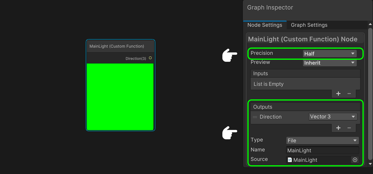
}We create a Custom Function Node. We are going to use this node to obtain the lighting direction configured in our scene. The first thing we do is to configure the node and in Source look for the file called ‘MainLight.’ As the name we put ‘MainLight’ too. We add ‘Direction’ in the outputs and it has to be a Vector 3. We will also make the node precision equal to ‘Half.’ Now it is compiling perfectly.
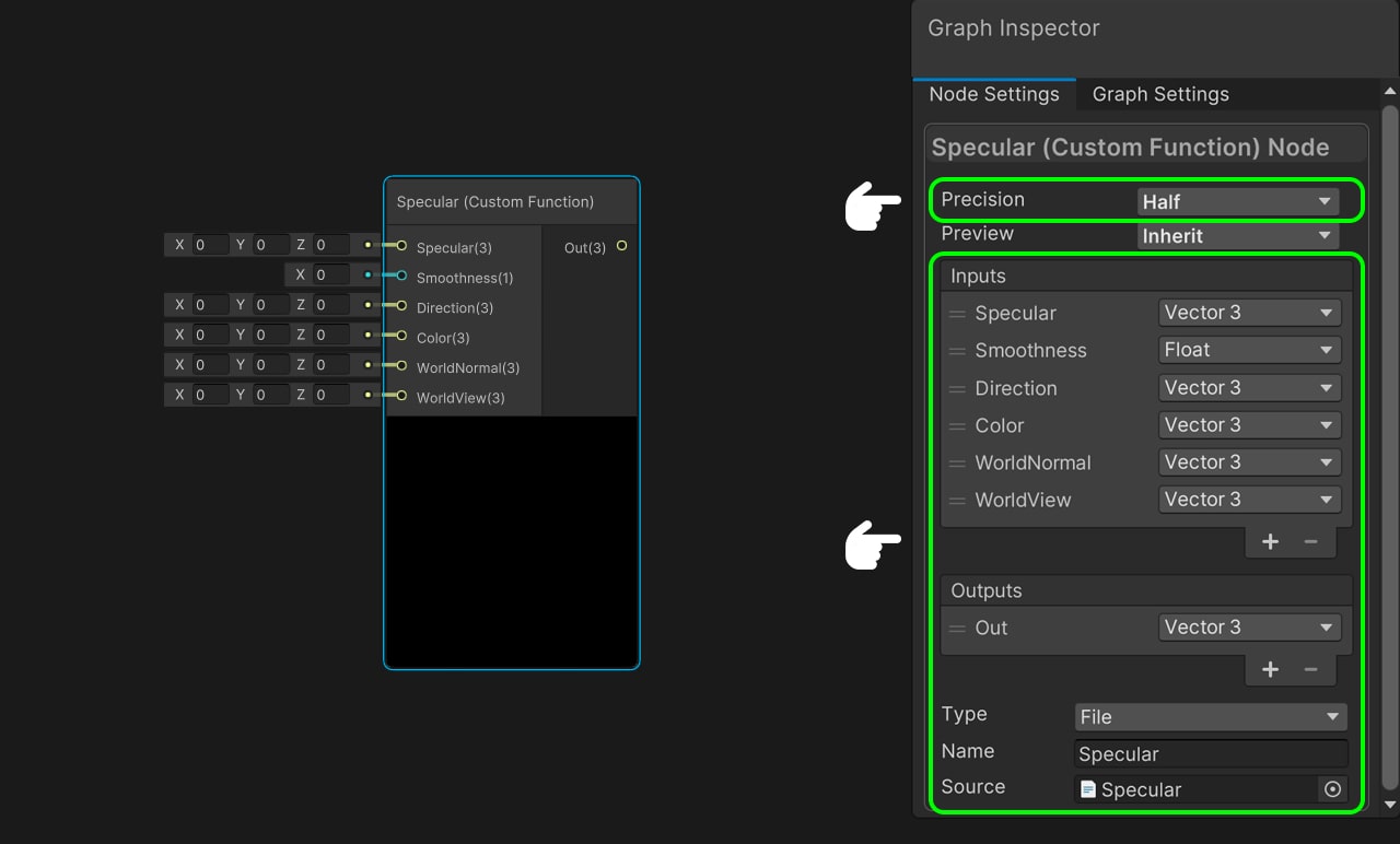
We create a new Custom Function node, this time to generate the specular. We go to the node configuration and look for the ‘Specular’ file. As the name we will use ‘Specular.’ We configure our inputs: we add a Vector 3 and call it ‘Specular,’ we add a Float and call it ‘Smoothness,’ we add a Vector 3 and we call it ‘Direction,’ we another add a Vector 3 and we call it ‘Color,’ we add a Vector 3 and we call it ‘WorldNormal’ and finally add a Vector 3 and call it ‘WorldView.’ As output we simply have to create a Vector 3 and call it ‘Out.’ We have to make the precision of the node equal to ‘Half.’ Done, our node is compiling perfectly.
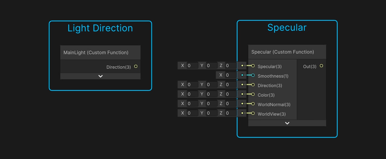
We group each node and name them ‘Light Direction’ and ‘Specular’ respectively.
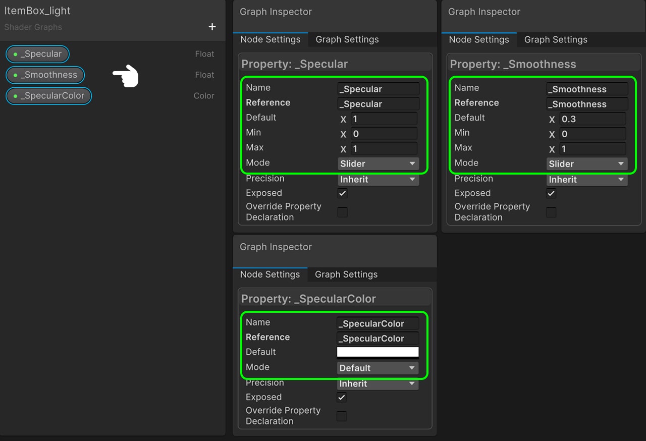
Now we have go to our blackboard and create some properties to dynamically modify the amount of Specular in the mesh. We create a Float, we call it ‘Specular’ and it has to be a Slider between 0 and 1 with 1 by default. We create another Float, we call it ‘Smoothness’ and it has to be a range between 0 and 1 with 0.5 by default. Finally we create a color and call it ‘_SpecularColor.’ It will be white by default.
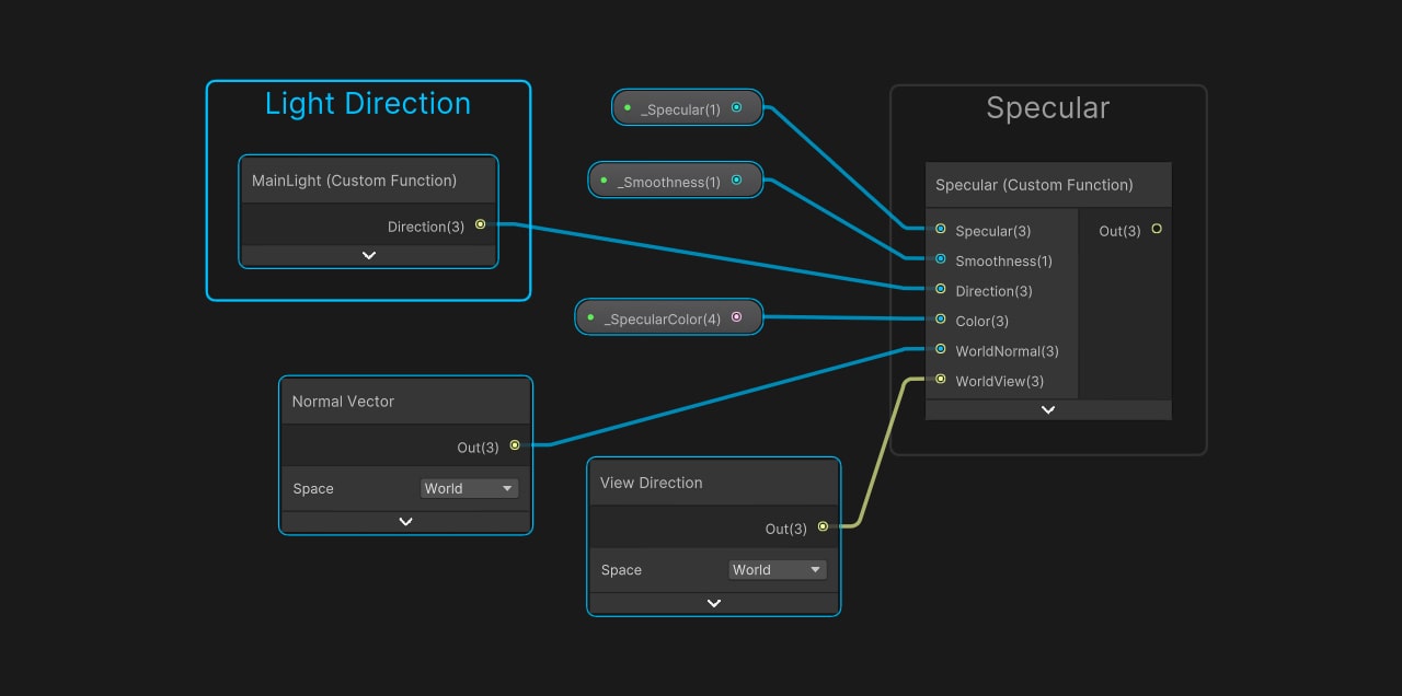
We drag the properties to the node area. And we connect ‘_Specular’ with Specular, ‘_Smoothness’ with Smoothness and ‘_SpecularColor’ with Color. For the direction we will pass the lighting direction. For WorldNormal we pass the Normal Vector node to have the normals in World Space and for World View we pass the View Direction node in World Space. We already have our Specular ready.
Now we only need to add this operation to the fresnel effect, for this, we bring an Maximum node and we pass both the Fresnel Effect and the Custom Specular. Finally we connect the output with the color of Fragment Shader. We save and return to Unity.
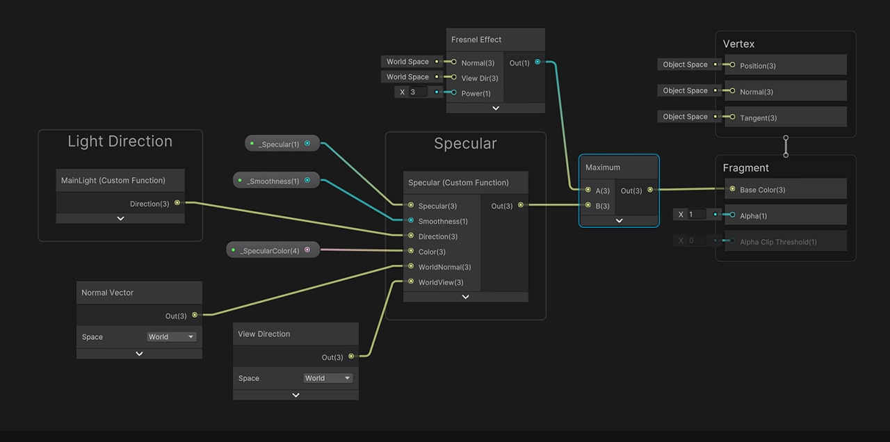
Our Specular effect is working perfectly.
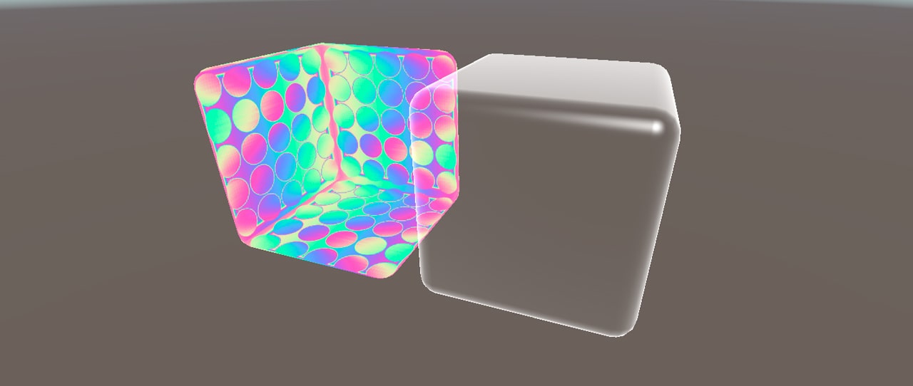
We position both GameObjets in the same position and parent ‘ItemBox_color’ with ‘ItemBox_light.’ It is possible that at this point, our material will be rendered last in the Zbuffer. To correct this, we simply have to go to the materials and make the ItemBox_color equal to 2998 in the Render Queue.
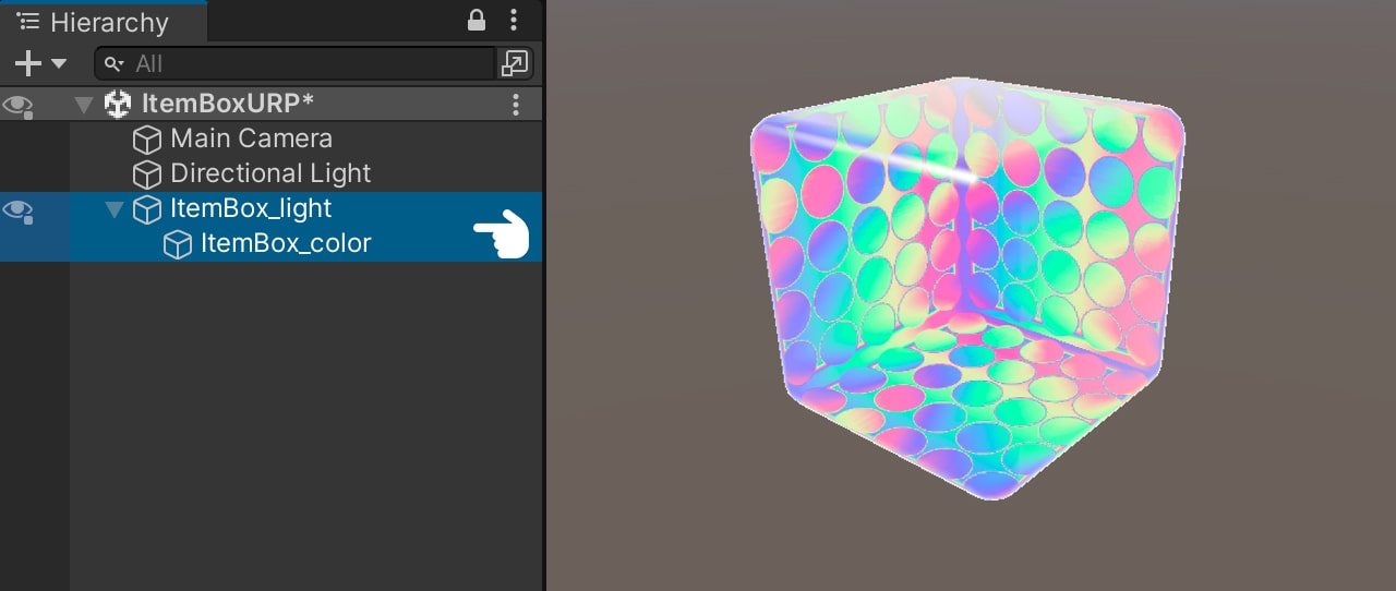
Adding the symbol
We only need the symbol in our effect. To do this, inside the ‘ItemBox_light,’ we create a ParticleSystem. We call it ‘ItemBox_symbol.’
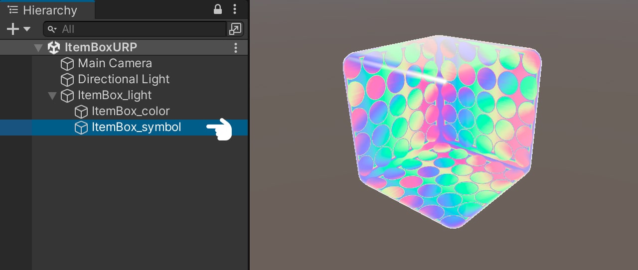
Before modifying our Particle System, we open the ‘ItemBox_symbol_URP’ shader. We go to the Blackboard, create a 2D Texture, we call it ‘_MainTex.’
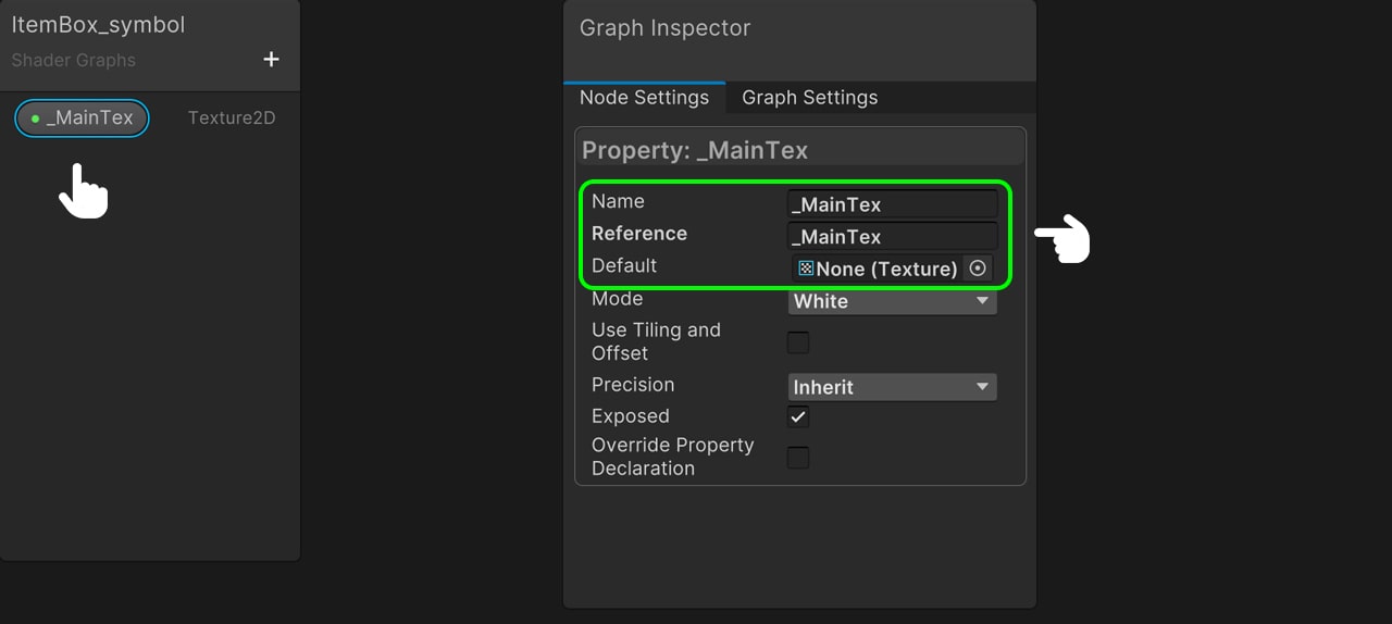
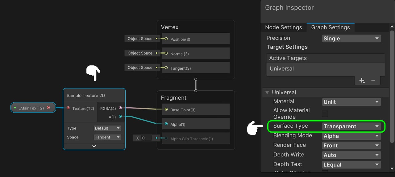
We drag the property to the node area, bring in a 2D Sample Texture node and connect both the color and the alpha in the Fragment Shader. This Surface Type will be ‘Transparent.’ We save it and return to Unity.
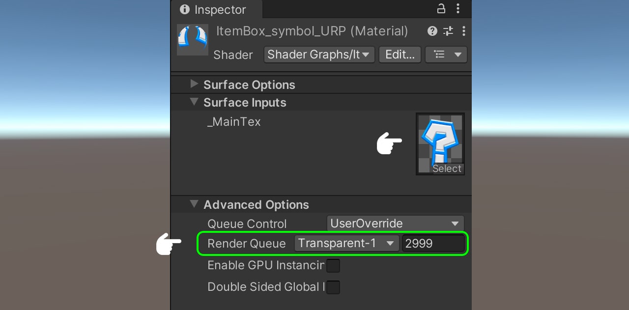
Select the material ‘ItemBox_symbol_URP’ and set the texture ‘ItemBox_symbol_tex.’ In the Render Queue, we make the ‘ItemBox_symbol_URP’ equal to 2999 to correct the rendering order.
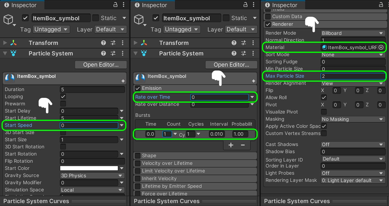
Then we will configure our Particle System to correctly display our symbol. To do this, we will first deactivate the Shape module since it will not be used. In the Main module we set the Start Speed equal to 0. Then in the Emission module we set the Rate Over Time equal to 0 and create a Burst with only 1 particle per cycle. Before finishing, we have to go to the Renderer module assign the ‘ItemBox_symbol_URP’ in the material property and we put the Max Particle Size equal to 2.
Final effect
Our effect is ready. If we press play, we can see how the effect works correctly.
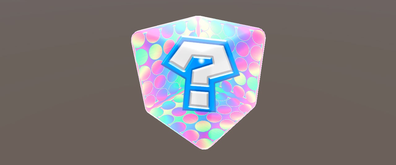
In conclusion, throughout this tutorial, we have learned how creating Mario Kart Item Box using Shader Graph in Unity.

